with Activankle or Swimankle
-
Swim, snorkel or scuba, with or without fins.
-
The Activankle easily locks into the walking position when you're finished.
-
Constructed of non-corroding Delrin and stainless steel.
-
The Activankle has a protective neoprene cover to keep sand out.
Swimming

- Unlocked, the Activankle flexes freely in a single axis with no rotation or lateral movement
- The Activankle is unlocked for snow skiing. See Video Here
Snow Skiing
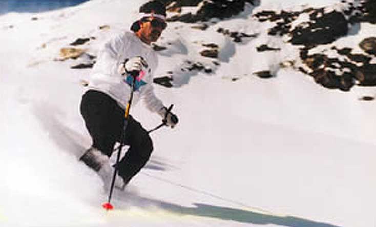
- The unlocked Activankle allows unlimited dorsiflexion for a comfortable natural position.
- The Activankle easily locks into the walking position when you're finished.
Jet Skiing

Made in USA

- Constructed of non-corroding Delrin and stainless steel
- Easy to Use Locking System
- May be used in most lower limb prosthesis
- Uses 10mm Footbolt and Standard 4 Hole Pattern
Swimming
The Swimankle locks in two positions for walking or swimming.
The Swimankle uses the same 70-degree plantar flexion as the Activankle for optimum swimming performance.
Unlike the Activankle, the Swimankle does not dorsiflex when unlocked.
Unlike the Activankle, the Swimankle does not have a protective cover.
Use in sandy conditions is not recommended.
Walking
When locked into walking mode, a large bearing surface on its lower component easily accomodates the higher vertical loads expected, leaving only residual loads on the stainless steel pivot. (sketch below)

The Swimankle is manufactured using the latest state of the art CNC equipment and manufacturing processes to ensure maximum reliability and ease of operation.
Made in USA
Swimming
Skiing
Rowing
All Three
Swim and Ski Prosthesis - Introduction
Any lower limb amputee will find it less physically demanding to swim with a fully plantar flexed prosthesis. Whether the individual is trying to set new speed records or just casually swimming, wearing a swimming prosthesis will reduce the amount of energy expended to move through the water. The single amputee becomes bilaterally symmetrical. Each arm stroke will be the same whether or not he or she is kicking for power. For the bilateral amputee, the legs will act like the keel of a boat. They will keep the bilateral going in a straight line and will stop the torso from penduluming with each stroke, thus reducing energy expended.
My name is Michael Ross, and I am the inventor of the Activankle.I am a bilateral BK who grew up in Southern California. Surfing, sailing, scuba diving, swimming competitively and water polo were major parts of my life. After my accident, it was important to me to be able to resume my water activities. Thus the Activankle was developed. I make no claim that this is the perfect device for swimming or other water activities, but it does the task it is intended to do. However, what you attach to the Activankle will make a noticeable difference in the performance of the swim prosthesis. Even for the amputee not interested in performance, the following information is useful for making a prosthesis that will hold up to the rigors of water and salt. After several prototypes, I found that the swim leg that works best is a hollow exoskeletal leg with a Symes foot.
The advantage of exoskeletal over endoskeletal (without foam) is increased hydrodynamic efficiency. The exoskeletal allows the water to flow undisturbed along the length of the leg and onto the foot. This could be accomplished with a foam covered endoskeletal leg but foam has a distinct tendency to absorb water and even if the foam is waterproofed, it will create too much positive buoyancy. By drilling two holes in the hollow section of the exoskeletal leg and allowing water to fill this cavity, excess positive buoyancy is eliminated. When a foam-covered foot is attached to the hollow exoskeletal swim leg, ideal positive buoyancy is attained. A Symes foot is another major factor for increasing hydrodynamic efficiency. When the Activankle is bolted to a Symes foot, the Activankle pivots from a point closely resembling the natural ankle joint. When these two are attached to the exoskeletal leg and fully plantar flexed, the top of the Symes foot will line up evenly with the anterior part of the leg. Water flowing undisturbed along the leg and directly onto the top surface of the foot is what allows the foot to generate power.
Suspension is very important. In the water, the prosthesis should feel as if it were bearing weight. If not, each kick will allow the residual limb to wobble inside of the socket, creating friction, which everyone knows is not good, and the energy will not be fully transferred to the foot. Silicone, urethane and latex suspension sleeves, work very well. They also keep water out. The addition of an auto expulsion valve creates superior suspension. For those using a pin suspension liner such as Iceross, Alps or Alpha Liner, the only shuttle locks I have recently seen two that appear to be water, salt and contamination proof are Coyote Design's Air-Lock and Fillauer's Gator Grip Lock. Whether you build endoskeletal or exoskeletal, the components used should be waterproof and corrosion resistant to salt. Kingsley's Steplite is Rampro's choice of foot. Water will not damage this foot. It has a graphite keel, the foam does not absorb water, and it can be ordered in several heel heights including flat. A flatty is ideal for use around the water where barefoot is usually the norm. 4C's Waterproof Symes and Ohio WillowWood's Impulse Symes will also work well. A lightweight aqua shoe with no heel will protect the prosthetic foot and the real foot.
If you decide to build a hollow exoskeletal, you can laminate a pyramid into the distal end of the leg. If you laminate a 4-hole block to the distal end, the threads should be stainless steel. Aluminum threads in saltwater is a definite no-no. If the leg will also be used for snow skiing, a low profile rotatable pyramid adapter should be used. Snow skiing typically requires the foot to be toed out 4 to 8 degrees. Rampro has stainless steel pyramid adjustment set screws. Pyramids and pyramid adapter should be either Titanium or stainless steel. The hollow exoskeletal leg with a pyramid interface also makes an ideal ski leg. The unlocked Activankle mounted to a Symes foot flexes from the same place as the human ankle and the ski boot manufacturers do know where the human ankle flexes. The hard exoskeletal leg solidly transfers energy to the tongue of the ski boot. The pyramid system easily allows for proper alignment and the rotatable adapter allows the toe to be set correctly.
The only optional modification for a ski leg would be the addition of a threaded stainless steel plate (approx.1 1/2" x 3/4" x1/8") laminated into the leg. Placement of the plate depends on the brace used. (e.g. For a Townsend brace, approximately 3" or 8cm below the patella.) This will allow a hard knee brace to be securely attached to the prosthesis. A matching hole needs to be drilled in the brace to accommodate the bolt or set screw protruding from the threaded plate. I use a partially threaded 1/4-20 bolt with 1/8" of threads. Cut off the bolt head so that the end of the non-threaded (smooth) bolt section is flush with the surface of the brace. A screwdriver slot can be cut into the end of the bolt with a hacksaw for easy install and removal of the bolt. With the easy to take on and off brace on top of my suspension sleeve, I have great suspension, extra stability and added safety.
If you decide not to fabricate the Hollow Exoskeletal leg yourself, Rampro can refer you to a fabrication lab that has fabricated over 100 swim legs using the Activankle or Swimankle. The Hollow Exoskeletal leg is fabricated for you from a walking alignment. Call Rampro for details. I hope this will answer a lot of questions. I do not consider this the only way to make a swim or ski prosthesis, but it works well for me as you can see in these video clips. Any comments or responses will be gladly accepted.
Sincerely,
Mike 
Activankle and Swimankle Installation Instructions
Read Entire Instructions Before Installing
1. Foot Bolt Installation
Use a 10mm bolt. Rampro supplies a 10m x 20m stainless steel bolt for use with the Kingsley Steplite or a 10m x 30m stainless steel bolt for use with most other Symes feet. ** VERY IMPORTANT **- Bolt should not exceed 1/2" or 13mm above the mounting surface of the foot. If these limits are exceeded damage to the ankle will occur and the warranty will be void. Do not stack lock washers if the bolt is too long. Cut the bolt to the proper length. If footbolt insert does not have a flange with 4 shallow holes, tighten foot bolt to 15 foot pounds or 180 inch pounds or 2.1 kilograms per meter. Do not over tighten. Do not use Lok-tite or any other bolt adhesive. Do not use lock washers. Do not stack washers. If footbolt insert has a flange with 4 shallow holes (Activankle 91-100 and later or Swimankle 3-101 and later), tighten footbolt according to foot manufacturers specifications or industry standards.
2. Foot Modification
Some foam will need to be removed on the medial side so as to access the ankle handle. The foam on the posterior side should be removed or ground very thin so as not to inhibit the ankle from plantar flexing. Bolt the ankle to the foot and mark the area to be removed. Remove the ankle from the foot and grind. Be conservative. Grind away only as much foam as is necessary to access the handle and allow the ankle to fully plantar-flex.
3. Drilling Dowel Pin Hole
To prevent ankle rotation, Rampro supplies a 5/32" x 1" stainless steel dowel pin. An optional dowel pin drilling template (ADPDT) is available from Rampro. Use a 5/32" drill. Drill 5/8" or 16mm aft (posterior) of foot bolt center. Drill 5/8"-11/16" or 16mm-18mm deep. Install dowel pin and ankle to foot. Arrow on top of ankle points forward (anterior). 5. Attachments Titanium parts are recommended for weight and corrosion resistance. The ankle accepts a standard 4 hole pattern. Rampro supplies 4 - 6 x 20mm flat socket head stainless steel screws. Tighten these to 40 inch pounds. Do not use Lok-tite or any other bolt adhesive. Stainless steel adjustment set screws are available from Rampro.
Activankle Operating Instructions
Unlock Ankle:
Rotate the D-ring handle 180° (1/2 turn) in the direction of the unlock arrow until it stops. It is not necessary to pull on the D-ring. Rotate D-ring with thumb and index finger. Note: Do not store the Activankle in the locked walking position when the Activankle is new. The locked walking position requires a break-in period before the ankle will unlock easily from this position. If it is difficult to start the rotation of the D-ring handle when unlocking from the walk position, extra thumb or hand pressure may be necessary. Do not use tools to rotate handle.
Positioning Foot:
Move the foot to the desired walk or swim position. The Activankle is in the swim position when fully plantar flexed. The Activankle is in the walk position when the top and bottom surfaces are parallel. A slight resistance will be felt when moving the Activankle to the walk position. When resistance ceases, the Activankle is ready to lock.
Lock Ankle:
The Activankle must be very close to the walk or swim position to lock. Rotate the D-ring handle 180° (1/2 turn) in the direction of the lock arrow until it stops. If the handle will only partially rotate, (do not force), then turn the handle back to the unlocked position and reposition the foot slightly. The Activankle must be very close to the walk or swim position to lock or binding will occur. If the handle has become bound between the lock and unlock positions, move the Activankle to the correct walk or swim position and then continue to rotate handle. Note: This is more easily accomplished when the Activankle is attached to a foot and a prosthesis.
Tips:
When the Activankle is new, it may be necessary to apply more pressure to start D-ring rotation when unlocking the walk position. " The Activankle must be very close to the walk or swim position to lock or binding will occur. " The Activankle is intolerant of sand or dirt. If the neoprene cover becomes cut or torn, it is easily repaired with neoprene cement. Don't wait. Repair it as soon as possible. " If the D-ring handle becomes difficult to rotate, do not force with pliers or any other tool. It is time to disassemble and clean. If the Activankle stops functioning properly, use the cleaning kit that came with the Activankle or the Activankle may be returned to Rampro for cleaning. ($35 + shipping) The Activankle may also be used for snow skiing or rowing in the unlocked position. Snow skiing in the locked position will void warranty.
Activankle Cleaning Instructions
Read Entire Instructions Before Proceeding
Tools Required:
Flat screw driver, #2 Phillips screw driver, Bushing Puller (ACK), clean cloth, Teflon grease

A. |
Unlock the Activankle. |
B. |
Remove D-ring (12) and D-ring cap (13). Cut nylon tie-wraps and remove neoprene cover. |
C. |
At a point near the LOWER DOWEL (15), insert a flat-blade screw driver under the END CAP (1) lip. Pry up and remove END CAP.Pull one layer of nyglass over the felt (optional). |
D. |
Using a Phillips screw driver, remove MACHINE SCREW (2). |
E. |
Remove WASHERS (3 and 6), SPRING (5) and SLEEVE (4). If any of these items remain lodged in the center of the CAM (8), they can be pushed out after the HANDLE ASSEMBLY (10 thru 14) is removed in step 1.f. |
F. |
Pull the HANDLE ASSEMBLY from the UPPER and LOWER ANKLE (19 and 20). |
G. |
Insert shaft of Bushing Puller into CAM (8). |
H. |
Repeat step (1.g) to remove the other bushing. |
I. |
Removing the cam from the ankle assembly requires accurate alignment of the bushing holes in the upper ankle and the large diameter (lobe) of the cam. Grasp the ankle assembly in both hands and while exerting thumb pressure on the cam end, slowly pull and rock at the ankle pieces until alignment is close enough to push out the cam. In some extreme cases it may be necessary to tap the cam out after proper alignment. |
J. |
Separate the upper and lower ankle pieces. No further disassembly is required for cleaning. |
2. CLEANING |
|
A. |
Wipe all parts thoroughly with a clean cloth. Soap and water or a mild solvent are OK. *If parts are scored from sand, use a fine grit sandpaper or emery cloth to smooth scratches. . |
3. REASSEMBLY |
|
A. |
Apply a thin coat of teflon grease in the following places: l - Outside surface of CAM (8). ll - The top groove, the large diameter bore and the vertical sides of the LOWER ANKLE (20). lll - The inside bore of the two BUSHINGS (7 and 9). lV - The small diameter shaft of the HANDLE BODY (11) and the WOODRUFF KEY (10). |
B. |
Slide the upper and lower ankle pieces together and align the cam and bushing holes. Make sure that the upper and lower ankle halves are matched (front and rear) correctly. |
C. |
Insert the cam in the upper and lower ankle bushing and cam holes with keyway for woodruff key (10) on the same side of the ankle as the HANDLE LOCKING PIN (18). Press in place. *If keyway for woodruff key (10) is at both ends of the cam, note the center hole diameter difference at each end of the cam. Insert the cam so that the cam's smaller hole end is on the same side of the ankle as the HANDLE LOCKING PIN (18). |
D. |
Note the two small puller plate attachment holes in each bushing. With these holes *facing out*, press both bushings into the ankle bushing holes. It may be necessary to tap the bushings in place. |
E. |
Align the WOODRUFF KEY (10) and install the HANDLE BODY (11) into the cam hole. Position over HANDLE LOCKING PIN (18). |
F. |
Refer to parts breakdown drawing and place items 3 thru 6 over the MACHINE SCREW (2). Apply a drop of Lok-tite to the threaded end of the screw and install this parts group into the hole at the other end of the cam. Do not overtighten screw. It may be necessary to loosen screw 1/8 to 1/4 turn for handle to operate smoothly. |
G. |
Snap END CAP (1) into place. |
H. |
Reinstall neoprene cover, D-ring and D-ring cap. |
I. |
Install and securely tighten two new tie-wraps. Reassembly is complete. |
If footbolt insert does not have a flange with 4 shallow holes , tighten foot bolt to 15 foot pounds or 180 inch pounds or 2.1 kilograms per meter. Do not overtighten. Do not use Lok-tite or any other bolt adhesive. Do not use lock washers. Do not stack washers. If footbolt insert has a flange with 4 shallow holes (Activankle 91-100 and later), tighten footbolt according to foot manufacturers specifications or industry standards. Use of Lok-tite or lock washers is OK. |
|

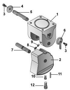
Swimankle Instructions
The Swimankle is locked when the HANDLE (6) is in the 6 o'clock position. To unlock, rotate HANDLE forward and up. Move foot to maximum plantar-flexed position for swimming then rotate HANDLE back to locked position. Ankle must be fully plantar-flexed or in correct walk position in order to lock.
Converting ankle to left or right operation
For BK's, the Swimankle handle is most easily operated when handle is on the medial side of the ankle. For AK's, it may be necessary to try both medial and lateral positions and let the patient decide. Use a 3mm Allen wrench to remove SCREWS (3). Move HANDLE and END CAP (4) to opposite sides of ankle and replace SCREWS.
Servicing
Tools required :
3mm, 4mm or 5/32" and 3/32" Allen wrenches, Teflon or silicon grease
1. Disassembly
a) Remove ankle from foot. Unlock ankle. Insert 5/32" or 4mm Allen wrench into footbolt hole and remove PIVOT PIN CAP SCREW (10). Remove PIVOT PIN (7) and separate UPPER (1) and LOWER (2) ankle halves.
b) If it is necessary to remove and clean LOCKING PIN (5), use a 3/32" Allen wrench to loosen TENSION SET SCREW (8). Loosen 5 or 6 full turns. Only remove HANDLE or END CAP that is on the same side of ankle as the TENSION SET SCREW. Remove LOCKING PIN.
2. Cleaning
Wipe all parts thoroughly with a clean cloth. Soap and water or a mild solvent is OK.
*If parts are scored from sand, use a fine grit sandpaper or emery cloth to smooth scratches
3. Reassembly
a) Apply a thin coat of teflon or silicon grease to vertical sides of LOWER ANKLE HALF, PIVOT PIN and LOCKING PIN. If HANDLE has been removed, apply grease to area where square hole of HANDLE and square end of LOCKING PIN contact each other, otherwise do so after reassembly.
b) Insert LOCKING PIN in unlocked position.
Do not force LOCKING PIN past TENSION PIN (9). If necessary, depress TENSION PIN with small tool and then finish inserting LOCKING PIN.
c) Attach HANDLE or END CAP.
d) Tighten TENSION SET SCREW. Tighten until HANDLE will not move, the loosen approximately ˝ turn. Adjust so that handle easily snaps into locked and unlocked positions.
e) Assemble ankle halves. Insert PIVOT PIN and align so that end marking on PIVOT PIN is vertical. Install and tighten PIVOT PIN CAP SCREW lightly (8-10 inch pounds). Do not overtighten. Overtightening will cause handle to not snap into locked and unlocked positions . Use Blue Lok-tite on this screw only.
If footbolt insert does not have a flange with 4 shallow holes, tighten foot bolt to 15 foot pounds or 180 inch pounds or 2.1 kilograms per meter. Do not overtighten. Do not use Lok-tite or any other bolt adhesive. Do not use lock washers. Do not stack washers.
If footbolt insert has a flange with 4 shallow holes (Swimankle 3-101 and later), tighten footbolt according to foot manufacturers specifications or industry standards.
Hollow Exoskeletal Fabrication Instructions
Slides by Darren Vincent viewed below


Laminate a stainless steel plate (appox.3/4"x1 1/2"x1/8") with a single threaded hole (1/4" or 6mm is sufficient) into the leg. Placement of the plate will depend on the brace used. (e.g. For a Townsend brace, threaded hole in plate should be approximately 3" or 8cm below patella on tibial centerline. After leg is completed, drill matching hole in brace. For best results use a partially threaded bolt. Cut threaded end so that 1/8" of threads remain. Cut smooth section of bolt so that when the brace is in place, the end of the cut off bolt will be flush with the surface of the brace. A screwdriver slot can be cut into the end of the bolt with a hacksaw for easy install and removal of the bolt.
These are fabrication guidelines. Quantity of material used will depend on the patient's weight and activity level.
Rampro can have your Hollow Exoskeletal leg fabricated for you from just a walking alignment. Call Rampro for details, or email vincent Vincent.
- Kingsley Steplite Symes
- Ohio Willow Wood Impulse Symes
- Coyote Design's Air-Lock
- Fillauer's Gator Grip Lock
- Kingsley
- Hosmer
- Fillauer
- American Prosthetic Components
Feet
Shuttle Locks
Pyramid Components
- Aulie Devices Water Sports Knee
- Handicapped Scuba Association International
- Scuba Diving Magazine (Check out the Gear Reviews, especially the fins)
- Canadian Association for Disabled Skiing - CADS Amputee Coalition of America - ACA
- Outback Mfg
(Precision CNC Machine Shop with CAD/CAM engineering. Our highly skilled team will direct you from conception to design to fabrication of your product).
Other Links
Made in USA